10Gbps 10G-SR Cisco Compatible 10 Gigabit SFP+ 10GBASE-SR SFP Transceiver – OM3 MMF – 850nm LC 300m
The PDT-SFP-03-10G-850-0030 is a low-cost, high-performance Small Form Pluggable (SFP) transceiver which is specifically designed for fiber communications with up to 10Gbps data rate, using OM3 MMF, over a distance of up to 300m.
This device is compatible with most vendors including Cisco, Parallax Digital Technologies, Meraki, D-Link, Ubiquiti, Supermicro, Netgear, Broadcom, Mikrotik, Robustel.
This VCSEL 10 Gigabit SFP+ Transceiver is designed to transmit and receive optical data over 50/125μm or 62.5/125μm multimode optical fiber (See Datasheet Tables).
This is the commercial variant of this product and a wider temperature range variant is also available as part of the Industrial SFP Product Line.
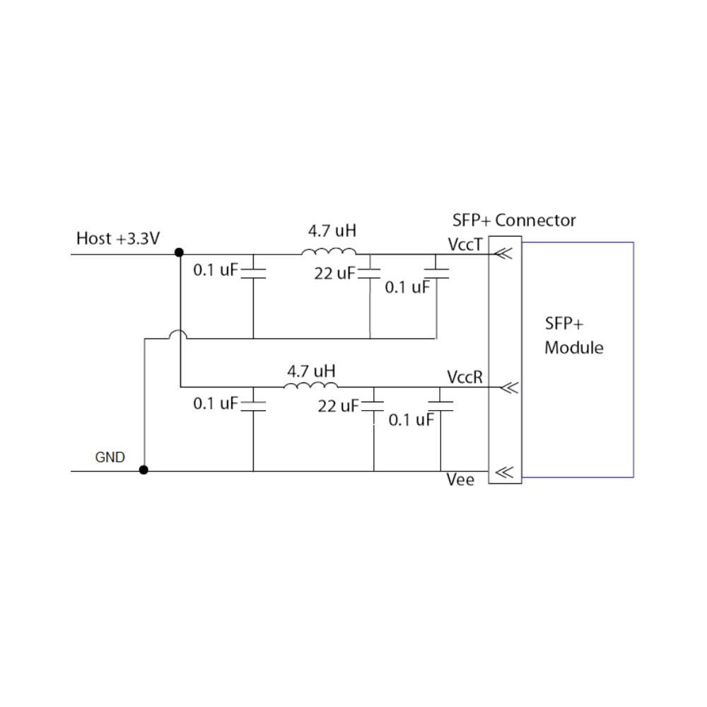
Host Board Power Supply Filters Circuit:
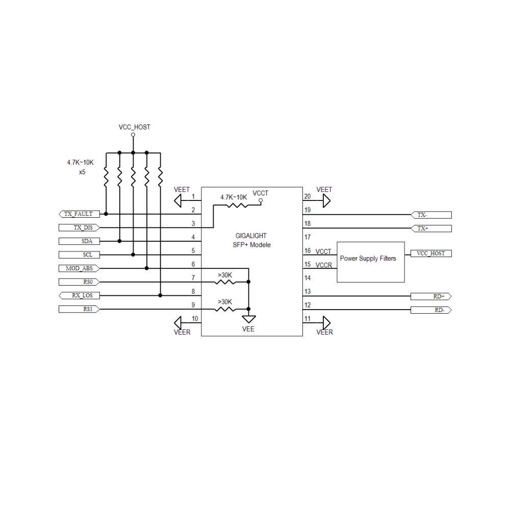
Host Module Interface:
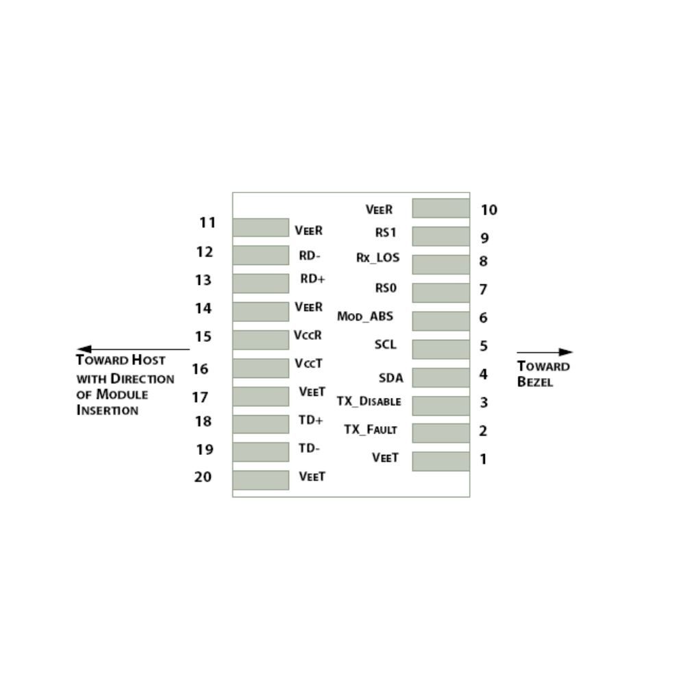
Pin Definitions:
| Pin |
Symbol |
Name/Description |
| 1 |
VEET [1] |
Transmitter Ground |
| 2 |
Tx_FAULT [2] |
Transmitter Fault |
| 3 |
Tx_DIS [3] |
Transmitter Disable. Laser output disabled on high or open |
| 4 |
SDA [2] |
2-wire Serial Interface Data Line |
| 5 |
SCL [2] |
2-wire Serial Interface Clock Line |
| 6 |
MOD_ABS [4] |
Module Absent. Grounded within the module |
| 7 |
RS0 [5] |
Rate Select 0 |
| 8 |
RX_LOS [2] |
Loss of Signal indication. Logic 0 indicates normal operation |
| 9 |
RS1 [5] |
Rate Select 1 |
| 10 |
VEER [1] |
Receiver Ground |
| 11 |
VEER [1] |
Receiver Ground |
| 12 |
RD- |
Receiver Inverted DATA out. AC Coupled |
| 13 |
RD+ |
Receiver DATA out. AC Coupled |
| 14 |
VEER [1] |
Receiver Ground |
| 15 |
VCCR |
Receiver Power Supply |
| 16 |
VCCT |
Transmitter Power Supply |
| 17 |
VEET [1] |
Transmitter Ground |
| 18 |
TD+ |
Transmitter DATA in. AC Coupled |
| 19 |
TD- |
Transmitter Inverted DATA in. AC Coupled |
| 20 |
VEET [1] |
Transmitter Ground |
Notes:
[1] Module circuit ground is isolated from module chassis ground within the module.
[2].should be pulled up with 4.7k – 10k ohms on host board to a voltage between 3.15Vand 3.6V.
[3]Tx_Disable is an input contact with a 4.7 kΩ to 10 kΩ pullup to VccT inside the module.
[4]Mod_ABS is connected to VeeT or VeeR in the SFP+ module. The host may pull this contact up to Vcc_Host with a resistor in the range 4.7 kΩ to10 kΩ.Mod_ABS is asserted “High” when the SFP+ module is physically absent from a host slot.
[5] RS0 and RS1 are module inputs and are pulled low to VeeT with > 30 kΩ resistors in the module.
Optical Characteristics:
| Parameter |
Symbol |
Min |
Typical |
Max |
Unit |
Notes |
| Transmitter |
| Centre Wavelength |
λt |
840 |
850 |
860 |
nm |
|
| Spectral Width (RMS) |
Pm |
– |
– |
Note1 |
nm |
|
| Average Optical Power |
Pavg |
-6.5 |
– |
-1 |
dBm |
2 |
| Extinction Ratio |
ER |
3.5 |
|
|
dB |
3 |
| Transmitter Dispersion Penalty |
TDP |
– |
– |
3.9 |
dB |
|
| Relative Intensity Noise |
Rin |
– |
– |
-128 |
dB/Hz |
12dB reflection |
| Optical Return Loss Tolerance |
|
– |
– |
12 |
dB |
|
| Receiver |
| Centre Wavelength |
λr |
840 |
850 |
860 |
nm |
|
| Receiver Sensitivity |
Psens |
– |
– |
-11.1 |
dBm |
4 |
| Stressed Sensitivity in OMA |
|
– |
– |
-7.5 |
dBm |
4 |
| LOS function |
LOS |
-30 |
– |
-12 |
dBm |
|
| Overload |
Pin |
– |
– |
-1.0 |
dBm |
4 |
| Receiver Reflectance |
|
– |
– |
-12 |
dB |
|
Notes:
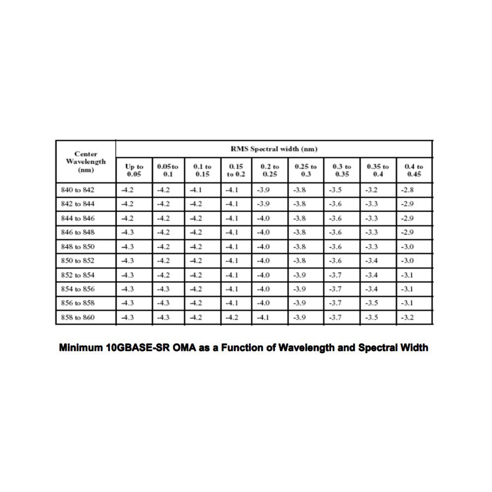
1. Trade-offs are available between spectral width, center wavelength and minimum OMA, as shown in table 6.
2. The optical power is launched into MMF.
3. Measured with a PRBS 231-1 test pattern @10.3125Gbps
4. Measured with a PRBS 231-1 test pattern @10.3125Gbps, BER ≤1×10-12
Performance vs Fiber:
| Fiber Type |
Min Modal Bandwidth @850nm MHz/*km |
Range |
| 62.5um MMF |
160 |
2~26 |
| 200 |
2~33 |
| 50um MMF |
400 |
2~66 |
| 500 |
2~82 |
| 2000 |
2~300 |
Low Speed Characteristics:
| Parameter |
Symbol |
Min. |
Typical |
Max |
Unit |
| Power Consumption |
|
|
|
1 |
W |
| TX_Fault,RX_LOS |
VOL |
0 |
|
0.4 |
V |
| VOH |
Host_Vcc-0.5 |
|
Host_Vcc+0.3 |
V |
| TX_DIS |
VIL |
-0.3 |
|
0.8 |
V |
| VIH |
2.0 |
|
VCCT+0.3 |
V |
| RS0,RS1 |
VIL |
-0.3 |
|
0.8 |
V |
| VIH |
2.0 |
|
VCCT+0.3 |
V |
Electrical Characteristics:
| Parameter |
Symbol |
Min. |
Typical |
Max |
Unit |
Notes |
| Data Rate |
|
– |
10.3125 |
– |
Gbps |
|
| Power Consumption |
|
– |
– |
1000 |
mW |
|
| Transmitter |
| Single Ended Output Voltage Tolerance |
|
-0.3 |
– |
4.0 |
V |
|
| C common mode voltage tolerance |
|
15 |
– |
– |
mV |
|
| Tx Input Diff Voltage |
VI |
400 |
|
1600 |
mV |
|
| Tx Fault |
VoL |
-0.3 |
|
0.4 |
V |
At 0.7mA |
| Data Dependent Input Jitter |
DDJ |
|
|
0.10 |
UI |
|
| Data Input Total Jitter |
TJ |
|
|
0.28 |
UI |
|
| Receiver |
| Single Ended Output Voltage Tolerance |
|
-0.3 |
– |
4.0 |
V |
|
| Rx Output Diff Voltage |
Vo |
300 |
|
850 |
mV |
|
| Rx Output Rise and Fall Time |
Tr/Tf |
30 |
|
|
ps |
20% to 80% |
| Total Jitter |
TJ |
|
|
0.70 |
UI |
|
| Deterministic Jitter |
DJ |
|
|
0.42 |
UI |
|
Recommended Operating Conditions:
| Parameter |
Symbol |
Min. |
Typical |
Max |
Unit |
| Power Supply Voltage |
VCC |
3.135 |
3.300 |
3.465 |
V |
| Operating Case Temperature (Standard) |
TC |
0 |
25 |
70 |
°C |
Absolute Maximum Ratings:
| Parameters |
Symbol |
Min. |
Max. |
Unit |
| Power Supply Voltage |
VCC |
0 |
+3.6 |
V |
| Storage Temperature |
Tc |
-40 |
+85 |
°C |
| Operating Case Temperature (Standard) |
Tc |
0 |
+70 |
°C |
| Relative Humidity |
RH |
5 |
95 |
% |
| RX Input Average Power |
Pmax |
– |
0 |
dBm |
Compliance Data:
| Feature |
Agency |
Standard |
Certificate / Comments
|
| Laser Safety |
FDA |
CDRH 21 CFR 1040 and Laser Notice No. 50 |
1120292-000 |
| Product Safety |
UL |
UL and CUL EN60950-2:2007 |
E347511 |
| Environmental protection |
SGS |
RoHS Directive 2002/95/EC |
GZ1001008918/CHEM |
| EMC |
WALTEK |
EN 55022:2006+A1:2007
EN 55024:1998+A1+A2:2003 |
WT10093759-D-E-E |


